
Troubleshooting - Throttle Circuit
The last part of the troubleshooting process is the throttle circuit. On most e-bikes, the throttle connects directly to the motor controller, however on the Fat Woody the throttle connects to the Cycle Analyst (CA) and then the CA connects to the motor controller.
Throttle Operation Overview
The throttle operates with a three (3) wire circuit. Pins 1 & 2 are +5.0vdc (red/black) provided by the CA to feed to the thumb throttle. Pin 3 is the return wire that indicates the position of the thumb throttle (based on voltage). It's referred to as the throttle input signal wire 'Thi'.
For example, with no throttle applied, the 'Thi' signal wire has 0vdc. At full throttle, the 'Thi' signal wire has +5.0vdc (or somewhere between +4.0-5.0v).
⚠️ Note: The voltage on pin 3 can only be measured with the thumb throttle connected.
Troubleshooting - Throttle Signals
There is a little risk when measuring the 5vdc supply voltage to the thumb throttle. If you inadvertently short pins 1 & 2, you run the risk of damaging the CA LCD Display output. The easier way to check the throttle signal is to let the Cycle Analyst measure the voltage for you. You can view real-time throttle Thi signal voltage in the Cycle Analyst Setup Menu.
Enter the Cycle Analyst V3.0 Setup Menu
The CA 'Setup Mode' is accessed by pressing and holding the left button for several seconds, or by holding the right button down while the CA is powered up. It is a 2-level deep menu list organized into 13 high level groups to let you adjust over 60 different settings. Remember pressing the left/right buttons toggle the menus left/right (or up/down), while pressing & holding the right button opens that menu or selects an item for modification.
There are also a few visual cues to help with navigation. Arrows on the left and right show when there are more items in the current menu level, while a straight bar indicates you are at the end of the list, and pressing the next button will take you up a level.
Once you enter the 'Setup Mode', you can toggle through a series of 13 category menus you can select from and/or modify. Each category menu provides a small preview line showing some of the key settings and real-time input signals for that category.
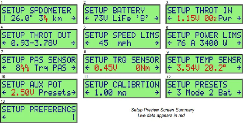
Once in the setup mode, pressing the left/right buttons will toggle through these 13 category menus.
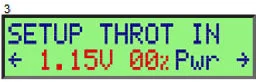
Navigate to Screen #3 - Setup Throttle In (Thi)
The preview line (line 2) shows measured voltage of throttle input, the equivalent % throttle that this voltage corresponds to, and the throttle mode (amps, speed, pass-thru, etc.)
The red data on the preview screen indicates real-time data and voltages. Moving the thumb throttle should increase/decrease the voltage shown in the preview screen. The normal range of voltage should vary from 0-5vdc.
Continue to cycle through the screens and you will exit Setup Mode, and be returned to the User Mode of operation.
For more detailed information on the Setup Menu, please visit the CA Programming section.
Note: Screen #4 - Setup Throttle Out (Tho)
Throttle Out (Tho) is the throttle signal from the CA to the motor controller (again, 0-5vdc). The CA does not display real-time Tho output voltage data.
This area of the setup menu actually only provides the ability to adjust CA output voltages based on thumb throttle input voltages.
The only way to measure the actual voltage output (Tho) of the CA is across pins 2 & 6 while the connector is connected and operating the throttle. Normal voltage values across these pins will vary from 0-5.0vdc depending on the position of the thumb throttle.
If any of the of the voltages above fall outside normal values or are not present, the Cycle Analyst has an issue and should be replaced. Replacement CA LCD Displays can be found in our parts shop.